

A derivative of the AD491 antenna, combining DGPS and dual band GPS/GLONASS reception with the addition of a passive dipole antenna for connection to a UHF (458MHz) radio modem without compromising performance.


Figure 1. AD540 antenna with a UHF antenna contained within the protruding section of the radome
_
Mechanical Specification
The 21cm diameter antenna case is machined from solid aluminium in two parts and hard anodised with a medium grey finish which is tough and extremely resistant to salt water corrosion.
The antenna is sealed to a minimum of IP67 with an ‘O’ ring preventing water ingress between the case halves; the limiting factor is the seal between the type N connector (TNC optional) on the antenna and the corresponding connector on the coaxial cable.
The radome is a 4 mm thick GRP pressure molding which can be painted to any colour requested.
The mass of the antenna is 3.2kg. Provision is made for an optional ground-plane extension.
Electrical Specification
Stacked patch antenna elements are used for dual band reception. The patches are stacked with the higher frequency band topmost. The radiation pattern is RHCP (+/- 0.5 dB at zenith) and omni-directional in azimuth, whilst good reception can be achieved down to 5° in elevation, figure 2.
The UHF antenna pattern is vertically polarised and uniform in azimuth, radiating principally towards the horizon. The line of sight range is up to 20km, depending on mounting elevation and the power of the externally connected transmitter.
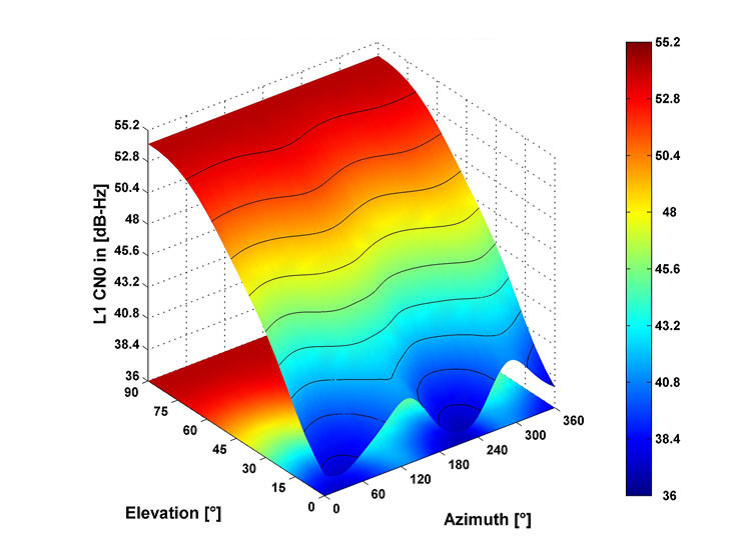
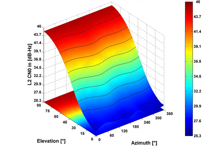
Figure 2. Antenna responses characterised at GPS L1 and L2 frequencies. Complete details for the antenna response and phase centre calibration are available on request.
A dual interdigital filter, carried over from the AD491, is used for DGPS and GPS/GLONASS upper (figure 3) and lower band reception (figure 4) to suppress near-band interference.
A single LNA is used for reception over the entire GNSS/DGPS frequency range. It employs a low noise GAsFet input stage followed by a silicon bipolar MMIC. The amplifier’s gain is factory preset usually to 42+/-2 dB, although other gains are available on request. A noise matching input circuit gives a total noise figure for amplifier and filter of <2.5 dB across each pass-band, figures 2 and 3. Supply voltage to the antenna is in the range 5V to 20Vdc (or 3V to 20Vdc on request) with a supply current of typically 45mA.


A single output is provided for GPS/DGPS and UHF, enabling connection to be made with a single coaxial down-lead. An optional multiplexer is available to separate the signals at the receiver/transmitter.
The range of the UHF link is dependent upon the line of sight distance to the horizon and the power from the connected transmitter.
Operating temperature range is -45°C to +70°C and storage temperature range is -55°C to +100°C.
The antenna complies with EMC requirements and is CE marked accordingly.