

A robust antenna with GLONASS and Galileo (E1,E5) dual band reception in addition to GPS and DGPS services incorporating interdigital filters for use in areas where general purpose antennae are inoperable due to L-band interference


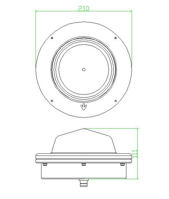
Figure 1. The AD491 antenna. The mounting brackets and U-bolts are supplied as standard
_
Mechanical Specification
The antenna case is machined from aluminium in two parts and hard anodised resulting in a rugged 21cm diameter base with a medium grey finish that is extremely resistant to salt water corrosion.
The antenna is sealed to a minimum of IP67 with an ‘O’ ring preventing water ingress between the case halves; the limiting factor is the seal between the type N connector (TNC optional) on the antenna and the corresponding connector on the coaxial cable.
The radome is a 4 mm thick GRP pressure molding, which can be painted to any colour required.
The antenna is 3.0kg in mass with the outline dimensions shown in figure 1. Provision has been made for an optional ground-plane extension.
Electrical Specification
Patch antenna elements provide dual band reception with the higher frequency patch stacked uppermost. The radiation pattern is RHCP and omni-directional in azimuth, whilst good reception can be achieved down to 5° in elevation, figure 2.
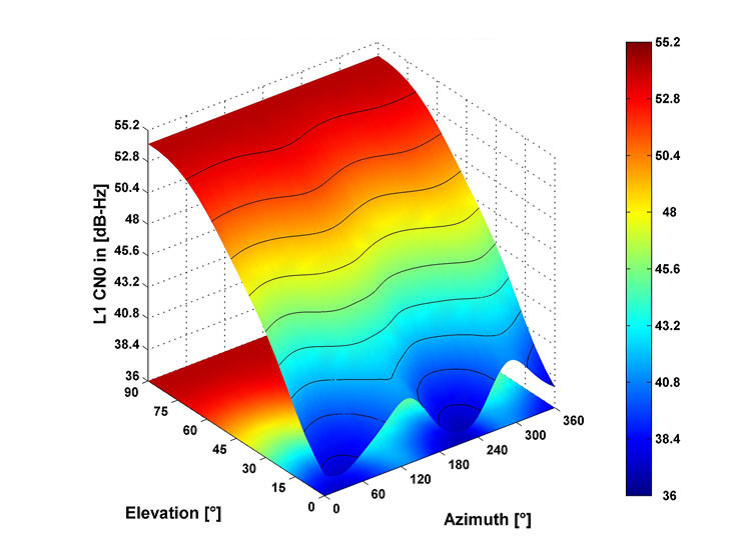
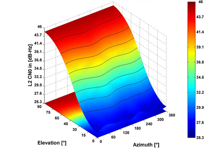
Figure 2. Antenna responses characterised at GPS L1 and L2 frequencies. Complete details for the antenna response and phase centre calibration are available on request.
Interdigital filters are used in the AD491 to provide the frequency response required. The insertion loss of the fifth order filter for 1525 to 1610 MHz reception is shown in figure 3. It incorporates an additional notch filter to attenuate out of band interference >1626MHz that, for example, may arise from an Inmarsat uplink. A forth order filter provides a passband for the reception over the frequency range 1164MHz – 1254MHz, figure 4.


A single low noise amplifier (LNA) is used across both frequency bands, which employs a low noise Gas Fet input stage followed by a silicon bipolar MMIC. The amplifier’s gain is factory preset usually to 43+/-2dB, although other gains are available on request. A noise matching input circuit gives a total noise figure for the amplifier and filter that is <2.5 dB across each pass-band.
The supply voltage to the antenna is phantom fed via its coaxial downlead and is in the range of +5V to +20Vdc with a current of typically 45mA usually sourced from the receiver.
Operating temperature range is -40°C to +70°C and storage temperature range is -40°C to +100°C.
The antenna is environmentally tested to EN60945 (clauses 8.2,8.3,8.4,8.7,8.8), and complies with EMC requirements for emissions EN55022 and immunity EN5008-1, and is CE marked accordingly